Media resilience in WebRTC refers to the ability of the system to maintain communication quality and reliability even in challenging network conditions. Modern real-time communications must function across diverse network environments with varying levels of stability. WebRTC implements several sophisticated mechanisms to ensure smooth audio and video experiences despite inevitable network issues.
This resilience is achieved through specific algorithms applied before, during, and after transmission of data packets. While the ideal approach is preventing packet loss entirely, these algorithms focus on minimizing data loss impact and ensuring a smooth user experience when losses occur.
The Challenge of Packet Loss
Every WebRTC project must anticipate and handle potential packet loss. In real-world networks, packet loss is unavoidable due to congestion, interference, hardware limitations, and other factors. Since packet loss is inevitable, WebRTC implements several strategies to maintain quality:
- Before transmission: Adding redundancy with RED and FEC
- During transmission: Implementing retransmission (RTX) protocols
- After transmission: Applying concealment methods (PLC)
Let's explore each of these approaches in detail.
Before Transmission: RED and FEC
Anticipating packet loss ahead of time, these methods focus on adding redundant information to the data stream to enable the receiver to reconstruct missing data.
Redundant Audio Data (RED)
Redundant Audio Data (RED) is a technique that carries older frames in the same RTP packet. It adds a 4-byte header per redundant block (as defined in RFC 2198) to encapsulate previously transmitted data along with the current audio payload. If the primary audio data payload is lost or corrupted during transmission, the receiver can use this lower-quality redundant information to replace the missing or damaged portion, improving the overall quality and completeness of the audio stream.
Forward Error Correction (FEC)
Forward Error Correction (FEC) is a technique used in WebRTC to enhance the reliability of data transmission by adding redundant information. The purpose of FEC is to allow the receiver to correct errors in the received data without the need for retransmission. This is particularly useful in real-time communication scenarios where re-transmitting data could introduce unacceptable delays.
Opus FEC Implementation
Opus FEC, built into the Opus Audio Codec, helps mitigate packet loss effects during audio transmission. It works by including a low-bitrate encoding of the previous audio frame within the next audio frame. If a packet containing audio data is lost, the receiver can use the redundancy information in the following packet to partially reconstruct the missing audio, reducing glitches and dropouts.
The FEC process involves:
- Redundancy Generation: The sender adds redundant information before transmitting media data packets, using techniques like XOR calculations, Reed-Solomon codes, or other mathematical approaches.
- Packet Transmission: Both original data packets and generated FEC packets are sent across the network.
- Recovery at the Receiver: The receiver checks for missing or corrupted packets and uses the redundant FEC information to reconstruct any missing data.
More information about FEC can be found in the RFC 8854 standard.
During Transmission: Retransmission via RTP (RTX)
Retransmission (RTX) is a mechanism to recover lost or damaged packets by retransmitting them. RTX is defined in the RFC 4588 standard. RTX works alongside FEC and other mechanisms to enhance the reliability of real-time communication. It is especially useful in scenarios where FEC does not adequately address packet loss, and retransmitting the missing packets is deemed more efficient than relying solely on error correction.
RTX Packet Structure

The OSN (Original Sequence Number) identifies the missing packet that the resent packet replaces. A separate RTX stream needs to be established specifically for carrying retransmission packets. The RTX payload is dynamic.
In the SDP, the RTX stream is linked to the original stream through an "apt" parameter, specifying the associated payload type. Here's a concrete example:
a=rtpmap:96 VP8/90000
a=rtpmap:97 rtx/90000
a=fmtp:97 apt=96;rtx-time=2000
In this example:
- Payload type 96 is used for VP8 video
- Payload type 97 is used for retransmission (rtx)
- The
apt=96parameter links the retransmission stream to the VP8 stream rtx-time=2000indicates packets will be kept available for retransmission for 2000 milliseconds
The apt (associated payload type) parameter maps the retransmission payload type to the original stream payload type. If multiple original payload types are used, multiple RTX payload types must be defined, each with its own apt parameter.
RFC 4588 - RTP Retransmission Payload Format
How RTX Works
-
RTP Payload Format: As defined in the previous section, RTX defines a special format for carrying retransmitted packets. This format includes information about the original packet, such as its sequence number and timestamp, allowing the receiver to identify and correctly reassemble the media stream.
-
Negative Acknowledgments (NACKs): When the receiver detects a missing packet, it sends a NACK to the sender. This NACK informs the sender about the specific packet that needs to be retransmitted.
-
Retransmission: Upon receiving a NACK, the sender transmits the requested packet again using the RTX payload format.
-
Recovery at the Receiver: When the receiver receives the retransmitted packet, it can fill the gap in the media stream and continue playback without any noticeable interruption.
RTX Implementation Considerations
-
RTX vs. FEC tradeoff: RTX works best on connections with relatively low round-trip times. For higher latency connections, FEC may be more effective.
-
Buffer management: The sender must maintain a buffer of recently sent packets to fulfill retransmission requests. The
rtx-timeparameter in the SDP controls how long packets remain available. -
Congestion awareness: RTX should be implemented with awareness of network congestion to avoid worsening network conditions with additional packets.
-
NACK aggregation: Implementations should consider aggregating NACKs for multiple lost packets into a single RTCP message to reduce overhead.
After Transmission: Packet Loss Concealment (PLC)
Packet Loss Concealment (PLC) is a technique used in WebRTC to mitigate the impact of packet loss on audio and video quality by concealing the effects of lost packets.
When data packets are transmitted over a network, some packets may be lost or arrive out of order due to network congestion, latency, or other issues. Losing packets can lead to glitches, artifacts, or disruptions in the media stream.
When a packet is not received, PLC attempts to reconstruct the missing or lost audio or video information. While it cannot replace the exact content of a lost packet, it can generate synthetic data to smooth out the playback and make the impact less noticeable to the end user.
Video PLC
Video PLC (VPLC) aims to mitigate the effects of dropped video packets during a call.
Here is a generalized working of Video PLC:
-
Missing Packets Detected: The decoder continuously monitors the incoming video data stream. If it identifies missing packets due to network hiccups, VPLC kicks in.
-
Filling the Gaps: Instead of leaving blank spaces or glitches where the missing packets should be, VPLC attempts to reconstruct the missing information. This can involve various strategies:
- Frame freezing: Most modern browsers fall back to this approach for losses longer than a frame interval - simply holding the last successfully decoded frame until new valid frames arrive.
- Temporal Concealment: This uses information from the previous and/or next video frames to estimate the missing parts.
- Spatial Concealment: This analyses nearby pixels within the same frame to infer the missing values.
- Motion Compensated Interpolation: This technique uses knowledge of video motion to predict how existing pixels should move and fill in the gaps. Unlike the other approaches, this sophisticated technique is rare outside dedicated hardware implementations (like set-top boxes and TVs).
-
Smoother Viewing: By replacing missing information with estimated data, VPLC aims to maintain a smooth and continuous video playback experience for the viewer. The reconstructed portions may not be perfect replicas of the original data, but they prevent jarring disruptions and improve the overall quality of the video call.
Video PLC Implementation Considerations
- Reference frames: Ensure critical reference frames (I-frames) have higher protection through FEC or other mechanisms to prevent cascading errors.
- Metrics monitoring: Track statistics like
freezeCountthrough the WebRTC getStats() API to evaluate video quality. - User feedback: Consider providing visual indicators when severe packet loss is affecting quality so users understand connection issues.
- Adaptability: Implement different PLC strategies based on content type - static content (like presentations) may benefit from different approaches than high-motion video.
Audio PLC
Audio packet loss concealment (PLC) is a technique used to minimize the impact of lost packets on the perceived audio quality. It attempts to mask the gaps left by missing data and create a smoother listening experience.
The default PLC implementation in WebRTC is NetEQ, an adaptive jitter buffer combined with a PLC engine. NetEQ intelligently manages incoming packets and adjusts buffering based on network conditions. You can learn more about NetEQ in the official documentation.
There are various ways NetEQ and other PLC systems mask packet loss in an audio stream:
- Silence insertion: This is the simplest approach, where the gap is filled with silence. However, this may create a noticeable audio glitch, but is computationally efficient.
- Waveform substitution: Replaces the missing audio with a copy of the previously received packet or a nearby segment. This works better for short losses but can sound bad for longer gaps.
- Statistical methods: Analyze surrounding audio to estimate the missing content based on statistical properties of speech or music signals. This offers better quality but requires more complex processing.
- Machine learning-based methods: Utilize AI algorithms trained on real-world audio to generate more realistic concealment. Google's generative model named WaveNetEQ is an ML-based replacement for traditional PLC, but it's only used on some Google clients, not in the default WebRTC implementation.
Audio PLC Implementation Considerations
- Jitter buffer tuning: The
jitterBufferTargetanddecayFactorfields in WebRTC'sNetEqControllerlet you trade latency for continuity. - Speech vs. music: Different PLC strategies work better for different audio content types. Speech can often be more effectively concealed than music.
- Buffer size tradeoffs: Larger jitter buffers improve PLC effectiveness but increase latency.
- Statistics monitoring: Use the following code to track how much audio is being concealed:
            // Get audio PLC statistics
pc.getStats().then(stats => {
  stats.forEach(report => {
    if (report.type === 'inbound-rtp' && report.kind === 'audio') {
      console.log(`Concealed samples: ${report.concealedSamples}`);
      console.log(`Concealment events: ${report.concealmentEvents}`);
      console.log(`Total samples duration: ${report.totalSamplesDuration}`);
    }
  });
});
In a previous lesson discussing Opus DTX, we explored how the SILK and CELT codecs deal with silent audio and try to create comfort noise or handle transitions between silent times and frames with audio. The same techniques can handle packet loss in an audio stream.
Comprehensive Resilience Strategy
Congestion Control Loop
An essential component of media resilience in WebRTC is the congestion control system that proactively adapts to network conditions:
-
GoogCC - A hybrid delay-plus-loss controller whose delay-based bandwidth estimator (BWE) probes for extra capacity before loss occurs.
-
Transport-Wide Congestion Control (TWCC) - An advanced feedback mechanism that provides precise one-way delay information for more accurate bandwidth estimation.
Learn more about Transport-Wide Congestion Control (TWCC)
Resilience tricks are only half the story - proactive bitrate adaptation through these congestion control mechanisms is equally critical for maintaining quality in challenging network conditions.
Multipath & Network Handover
Beyond media-level resilience, WebRTC also provides path resilience mechanisms:
-
Multiple simultaneous ICE candidates - Local, STUN, and TURN candidates enable path fail-over in case one network path becomes unavailable. Note that mDNS candidates are primarily for privacy (hiding host IPs) rather than providing path resilience.
-
"Connection oriented" ICE restarts - Enable seamless transitions between networks (e.g., from WiFi to cellular).
-
QUIC-datagram / WebTransport - Early tests show noticeably faster recovery (a few RTTs faster) compared to SRTP because QUIC ACKs are piggy-backed on the data path. It's worth noting that QUIC's loss-recovery (RFC 9002) is byte-level, while RFC 9221's datagrams ride on top without retransmission.
RFC 9221 - An Unreliable Datagram Extension to QUIC
Objective Quality Metrics
Modern WebRTC implementations expose several metrics to help monitor resilience performance. Here's how to access them:
            // Get resilience metrics from WebRTC stats API
pc.getStats().then(stats => {
  stats.forEach(report => {
    // Video metrics
    if (report.type === 'inbound-rtp' && report.kind === 'video') {
      console.log(`FEC packets received: ${report.fecPacketsReceived}`);
      console.log(`FEC packets discarded: ${report.fecPacketsDiscarded}`);
      console.log(`Frames frozen: ${report.freezeCount}`);
      console.log(`Frames decoded: ${report.framesDecoded}`);
    }

    // RTX metrics
    if (report.type === 'inbound-rtp') {
      console.log(`RTX packets received: ${report.rtxPacketsReceived || 0}`);
    }
  });
});
Consider exposing these metrics in your application's UI for live troubleshooting.
Visualizing Media Resilience
To better understand how RED, ULPFEC, and RTX fit together in the WebRTC stack, consider the following diagram showing how these mechanisms are multiplexed on the wire:
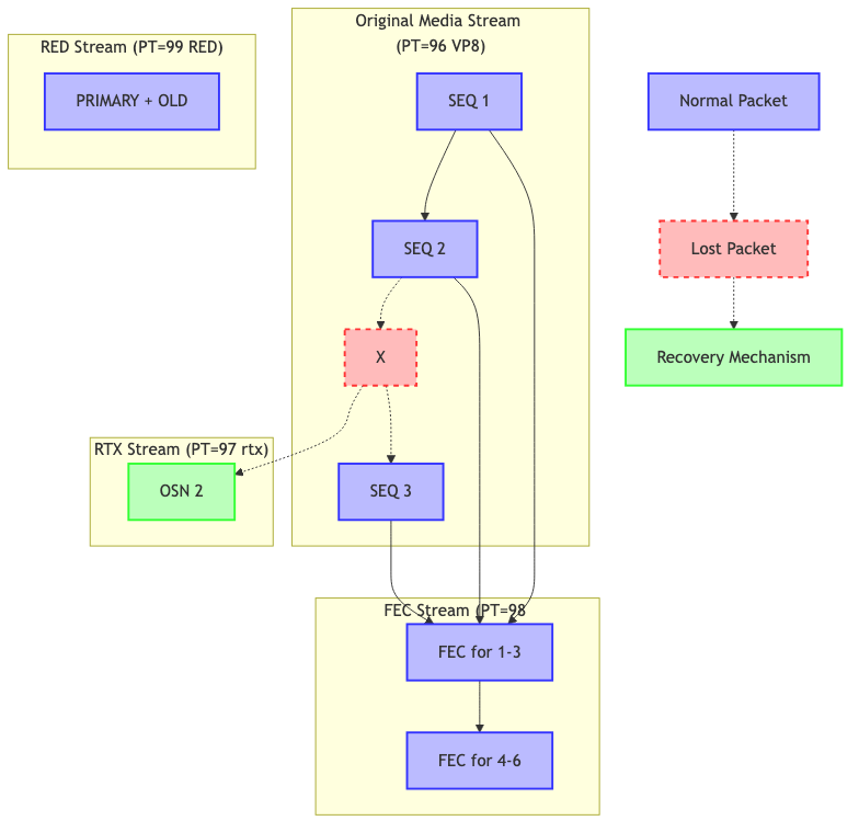
Key points from this diagram:
- Original stream - Regular RTP packets with a payload type for the media (VP8 in this example)
- RTX stream - Separate stream carrying retransmitted packets with Original Sequence Numbers (OSN)
- FEC stream - Separate protection stream with redundancy data for groups of packets
- RED stream - Packets containing both primary and redundant (older) data in the same packet
Note: RED is shown separately for clarity; in practice it reuses the original SSRC and sequence numbers.
The different approaches have different tradeoffs in terms of latency, bandwidth usage, and recovery capabilities. A comprehensive WebRTC implementation will often use multiple approaches adaptively based on network conditions.
Advanced Resilience Techniques
Beyond the basic mechanisms described above, advanced WebRTC implementations might also consider:
-
Simulcast and SVC: Using scalable video coding or simulcast to send multiple quality versions of video, allowing receivers to select the appropriate quality level based on network conditions. A recent Chrome experiment (2025-Q1) allows FlexFEC on the base layer only for SVC, reducing overhead by approximately 35%. (FlexFEC-03 is currently supported only in Chrome-based stacks and often disabled behind a feature flag).
-
Hybrid approaches: Combining multiple resilience techniques adaptively based on the specific characteristics of the current network conditions.
-
Cross-layer optimization: Coordinating application-layer resilience with transport-layer protocols (like QUIC) for more efficient packet recovery.
-
Bandwidth adaptation strategies: Implementing proactive quality reduction during network congestion rather than suffering packet loss that requires resilience mechanisms.
Practical Testing for Media Resilience
To ensure your WebRTC application handles adverse network conditions effectively:
-
Network condition simulation: Use tools like Network Link Conditioner (macOS), Clumsy (Windows), or tc (Linux) to simulate packet loss, jitter, and bandwidth limitations.
-
Quality metrics monitoring: Implement objective metrics (PESQ, POLQA, VMAF) and subjective testing to evaluate media quality under different network conditions.
-
Real-world testing: Test your application across various network types (WiFi, cellular, congested networks) and geographic locations.
-
A/B testing: Compare different resilience strategies to identify the optimal approach for your specific use case.
Conclusion
Media resilience in WebRTC involves a comprehensive approach to managing packet loss before, during, and after transmission. While there is no perfect solution for eliminating all effects of network instability, the combined application of RED, FEC, RTX, and PLC techniques provides a robust framework for maintaining communication quality even in challenging conditions.
By implementing these resilience mechanisms effectively in your WebRTC applications, you can deliver a significantly improved user experience that maintains quality and reliability across diverse and unpredictable network environments.